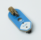
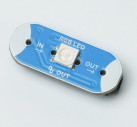
PeeCee Compute Kit: Difference between revisions
Evobi admin (talk | contribs) mNo edit summary |
Evobi admin (talk | contribs) mNo edit summary |
||
| (9 intermediate revisions by the same user not shown) | |||
| Line 1: | Line 1: | ||
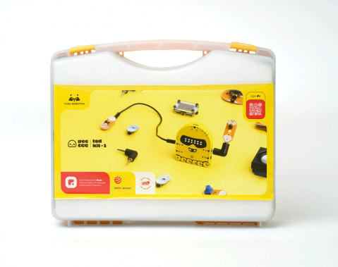
The PeeCee Compute Kit is your ultimate companion for diving into educational robotics with style and precision. Designed for schools, institutions, and anyone passionate about STEM, this versatile kit combines the powerhouse [[PeeCee TED|''PeeCee TED'']] with an array of components like sensors, motors, and servos to create a complete robotics playground. PeeCee TED itself is an advanced | [[File:Compute-kit 1.png|right|frameless|479x479px]] | ||
The PeeCee Compute Kit is your ultimate companion for diving into educational robotics or hands-on learning in STEM with style and precision. Designed for schools, institutions, and anyone passionate about STEM, this versatile kit combines the powerhouse [[PeeCee TED|''PeeCee TED'']] with an array of components like sensors, motors, and servos to create a complete robotics playground. PeeCee TED itself is an advanced iot and measurement device, making it perfect for projects that demand accuracy and adaptability. | |||
Whether you are experimenting with sensors, programming motorized robots, or measuring environmental parameters, the Compute Kit offers endless possibilities for innovation. Fully compatible with the PLODE platform, it empowers students and educators to easily code and simulate projects, ensuring a seamless learning experience. Built to last, the PeeCee Compute Kit is ideal for repeated use, making it a smart investment for classrooms, makerspaces, and robotics clubs. It fosters hands-on learning by encouraging creativity, logical thinking, and problem-solving skills. From crafting robots that bring imaginative ideas to life to tackling complex engineering challenges, this kit is a gateway to mastering robotics from the basics to the advanced. | Whether you are experimenting with sensors, programming motorized robots, or measuring environmental parameters, the Compute Kit offers endless possibilities for innovation. Fully compatible with the PLODE platform, it empowers students and educators to easily code and simulate projects, ensuring a seamless learning experience. Built to last, the PeeCee Compute Kit is ideal for repeated use, making it a smart investment for classrooms, makerspaces, and robotics clubs. It fosters hands-on learning by encouraging creativity, logical thinking, and problem-solving skills. From crafting robots that bring imaginative ideas to life to tackling complex engineering challenges, this kit is a gateway to mastering robotics from the basics to the advanced. | ||
| Line 5: | Line 6: | ||
If you are looking for a reusable, adaptable, and educational robotics solution, PeeCee Compute Kit is where your search ends. It is not just a kit—it is a toolkit for the future of learning, designed to inspire and nurture the innovators of tomorrow. | If you are looking for a reusable, adaptable, and educational robotics solution, PeeCee Compute Kit is where your search ends. It is not just a kit—it is a toolkit for the future of learning, designed to inspire and nurture the innovators of tomorrow. | ||
== | [[File:Peecee compute kit 1.png|left|frameless|495x495px]] | ||
Welcome to PeeCee, your gateway to turning big ideas into awesome robotic creations | |||
== Overview == | |||
Welcome to PeeCee, your gateway to turning big ideas into awesome robotic creations. The PeeCee Compute Kit combines hardware and software to enable users to design interactive systems. Its core component, the PeeCee TED unit, supports connectivity with various plug-in sensors and actuators via General-Purpose Input/Output (GPIO) ports. | |||
The kit integrates with the PLODE platform, which offers coding and simulation capabilities in multiple programming languages, including block-based coding, Python, and C, that make this kit a tech playground. Applications include real-time environmental monitoring, precise motion control, and multi-sensory robotics projects. | |||
=== What's Inside the Box: === | === What's Inside the Box: === | ||
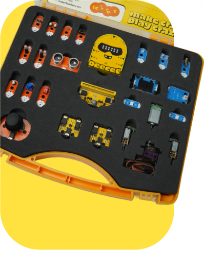
Open the box of the PeeCee Compute Kit and step into a world of endless possibilities. Designed for creative minds and curious learners, this kit equips you with all the tools needed to explore the realms of robotics and technology. Dive into hands-on learning and build, code, and innovate with ease. The PeeCee Compute Kit comes with everything you need to begin your journey, offering a solid foundation for all your STEM explorations. | Open the box of the PeeCee Compute Kit and step into a world of endless possibilities. Designed for creative minds and curious learners, this kit equips you with all the tools needed to explore the realms of robotics and technology. Dive into hands-on learning and build, code, and innovate with ease. The PeeCee Compute Kit comes with everything you need to begin your journey, offering a solid foundation for all your STEM explorations. | ||
''The kit comprises the following components:'' | |||
{| class="wikitable" | {| class="wikitable" | ||
!<small>SL NO</small> | !<small>SL NO</small> | ||
!<small>Component</small> | !<small>Component</small> | ||
| Line 31: | Line 31: | ||
|<small>N/A</small> | |<small>N/A</small> | ||
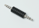
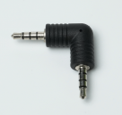
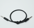
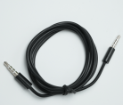
|<small>Computational Kit</small> | |<small>Computational Kit</small> | ||
|<small> | |<small>The main processing unit for all PeeCee projects.</small> | ||
|[[File:PeeCee | |[[File:PeeCee 1.png|frameless|142x142px]] | ||
|1 | |1 | ||
|- | |- | ||
| Line 45: | Line 38: | ||
|'''<small>PeeCee Shield</small>''' | |'''<small>PeeCee Shield</small>''' | ||
|<small>N/A</small> | |<small>N/A</small> | ||
|<small> | |<small>Additional GPIO and Motor Driver port</small> | ||
|<small> | |<small>Expands connectivity.</small> | ||
|[[File: | |[[File:Shield 1.png|frameless|143x143px]] | ||
|1 | |1 | ||
|- | |- | ||
| Line 61: | Line 47: | ||
|<small>Output</small> | |<small>Output</small> | ||
|<small>Integrated Circuit</small> | |<small>Integrated Circuit</small> | ||
|<small>Controls | |<small>Controls motor speed and direction based on commands.</small> | ||
|[[File:Motor | |[[File:Motor bridge.png|frameless|143x143px]] | ||
|2 | |2 | ||
|- | |- | ||
|<small>4</small> | |<small>4</small> | ||
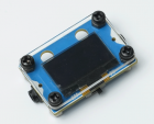
|'''<small> | |'''<small>128x64, 0.96” </small>''' | ||
'''<small>OLED Display</small>''' | |||
|<small>Output</small> | |<small>Output</small> | ||
|<small>Display</small> | |<small>Display</small> | ||
|<small> | |<small>Displays text, graphics, and project data</small> | ||
|[[File: | |[[File:Oled.png|frameless|140x140px]] | ||
|1 | |1 | ||
|- | |- | ||
|<small>5</small> | |<small>5</small> | ||
|'''<small>Servo Motor</small>''' | |'''<small>Tower pro MG90</small>''' | ||
'''<small>Servo Motor</small>''' | |||
|<small>Output</small> | |<small>Output</small> | ||
|<small>DC Motor with Gearing</small> | |<small>DC Motor with Gearing</small> | ||
|<small> | |<small>Enables precise control over angular movement.</small> | ||
|[[File:Servo | |[[File:Servo motor.png|frameless|143x143px]] | ||
|1 | |1 | ||
|- | |- | ||
| Line 106: | Line 73: | ||
|<small>Output</small> | |<small>Output</small> | ||
|<small>Electric Motor</small> | |<small>Electric Motor</small> | ||
|<small> | |<small>Generates rotational motion for various applications.</small> | ||
|[[File:DC motor.png|frameless|141x141px]] | |||
|[[File:DC | |||
|1 | |1 | ||
|- | |- | ||
| Line 123: | Line 82: | ||
|<small>Miniature</small> | |<small>Miniature</small> | ||
<small>DC Motor</small> | <small>DC Motor</small> | ||
|<small> | |<small>A compact motor ideal for small, precise movements.</small> | ||
|[[File:N20 | |[[File:N20 motor.png|frameless|141x141px]] | ||
|2 | |2 | ||
|- | |- | ||
|<small>8</small> | |<small>8</small> | ||
|'''<small> | |'''<small>Range</small>''' | ||
'''<small>Sensor</small>''' | |||
|<small>Input</small> | |<small>Input</small> | ||
|<small>Infrared</small> | |<small>Infrared</small> | ||
<small>Photodiode</small> | <small>Photodiode</small> | ||
|<small>Detects objects | |<small>Detects nearby objects and measures distance using infrared light.</small> | ||
|[[File:Range sensor 1.png|frameless|142x142px]] | |||
|[[File: | |||
|2 | |2 | ||
|- | |- | ||
|<small>9</small> | |<small>9</small> | ||
| Line 156: | Line 100: | ||
|<small>Input</small> | |<small>Input</small> | ||
|<small>Ultrasonic</small> | |<small>Ultrasonic</small> | ||
|<small>Measures</small> | |<small>Measures distance using</small> <small>high-frequency sound waves</small> | ||
<small> | |[[File:Ultrasonic sensor.png|frameless|144x144px]] | ||
|[[File: | |||
|1 | |1 | ||
|- | |- | ||
|<small>10</small> | |<small>10</small> | ||
| Line 172: | Line 108: | ||
|<small>Input</small> | |<small>Input</small> | ||
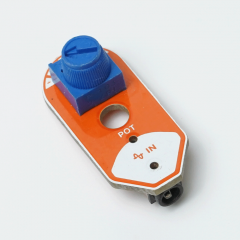
|<small>Variable Resistor</small> | |<small>Variable Resistor</small> | ||
|<small> | |<small>Adjusts voltage output to control input values.</small> | ||
|[[File:POT.png|frameless|141x141px]] | |||
|[[File: | |||
|1 | |1 | ||
|- | |- | ||
|<small>11</small> | |<small>11</small> | ||
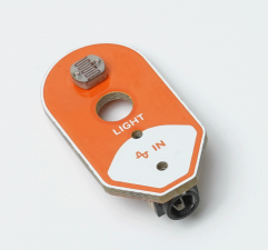
|'''<small>Light | |'''<small>Light Sensor</small><small>(LDR)</small>''' | ||
|<small>Input</small> | |<small>Input</small> | ||
|<small>Photoresistor</small> | |<small>Photoresistor</small> | ||
|<small> | |<small>Detects and measures ambient light levels.</small> | ||
|[[File:Light sensor.png|frameless|141x141px]] | |||
|[[File: | |||
|1 | |1 | ||
|- | |- | ||
| Line 205: | Line 125: | ||
|<small>Conductive /</small> | |<small>Conductive /</small> | ||
<small>Capacitive</small> | <small>Capacitive</small> | ||
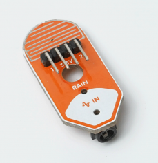
|<small>Detects the presence of water</small> | |<small>Detects the presence of water by identifying conductivity changes.</small> | ||
|[[File:Rain sensor | |[[File:Rain sensor 1.png|frameless|145x145px]] | ||
|1 | |1 | ||
|- | |- | ||
| Line 220: | Line 133: | ||
|<small>Input</small> | |<small>Input</small> | ||
|<small>Analog/Push Button</small> | |<small>Analog/Push Button</small> | ||
|<small>Provides | |<small>Provides directional movement data along with button inputs</small> | ||
|[[File:Joystick.png|frameless|140x140px | |[[File:Joystick 1.png|frameless|140x140px]] | ||
|1 | |1 | ||
|- | |- | ||
| Line 235: | Line 141: | ||
|<small>Input</small> | |<small>Input</small> | ||
|<small>Mechanical Switch</small> | |<small>Mechanical Switch</small> | ||
|<small> | |<small>Registers a press for user interaction.</small> | ||
|[[File: | |[[File:Button 1.png|frameless|146x146px]] | ||
|1 | |1 | ||
|- | |- | ||
|<small>15</small> | |<small>15</small> | ||
|'''<small>Dual Push</small><small>Button</small>''' | |'''<small>Dual Push</small> <small>Button</small>''' | ||
|<small>Input</small> | |<small>Input</small> | ||
|<small>Mechanical Switch</small> | |<small>Mechanical Switch</small> | ||
|<small>Detects button presses | |<small>Detects two separate button presses for dual functionality.</small> | ||
|[[File: | |[[File:Button 2.png|frameless|142x142px]] | ||
|1 | |1 | ||
|- | |- | ||
| Line 265: | Line 157: | ||
|<small>Input</small> | |<small>Input</small> | ||
|<small>Mechanical Switch</small> | |<small>Mechanical Switch</small> | ||
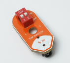
|<small> | |<small>Enables multiple on/off control settings</small> | ||
|[[File: | |[[File:Dip switch.png|frameless|142x142px]] | ||
|1 | |1 | ||
|- | |- | ||
| Line 281: | Line 166: | ||
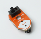
|<small>Mechanical Switch</small> | |<small>Mechanical Switch</small> | ||
|<small>Basic on/off switch</small> | |<small>Basic on/off switch</small> | ||
|[[File:Switch png.png|frameless| | |[[File:Switch 1.png|frameless|143x143px]] | ||
|1 | |||
|- | |||
|<small>18</small> | |||
|'''<small>LED</small>''' | |||
|<small>Output</small> | |||
|<small>Light Emitting Diode</small> | |||
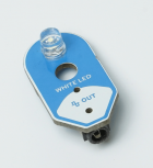
|<small>Provides visual feedback with a single light source.</small> | |||
|[[File:Led.png|frameless|153x153px]] | |||
|1 | |||
|- | |||
|<small>19</small> | |||
|'''<small>LED 2C</small>''' | |||
|<small>Output</small> | |||
|<small>Light Emitting Diode</small> | |||
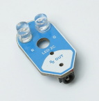
|<small>Offers an additional light indicator.</small> | |||
|[[File:Led 2.png|frameless|145x145px]] | |||
|1 | |||
|- | |||
|<small>20</small> | |||
|'''<small>Laser Module</small>''' | |||
|<small>Output</small> | |||
|<small>Laser</small> | |||
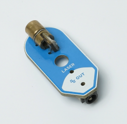
|<small>Emits laser beam for alignment</small> | |||
|[[File:Laser module 1.png|frameless|139x139px]] | |||
|1 | |||
|- | |||
|<small>21</small> | |||
|'''<small>RGB LED</small>''' | |||
|<small>Output</small> | |||
|<small>RGB LED</small> | |||
|<small>Provides multi-color visual feedback</small> | |||
|[[File:RGB LED 1.png|frameless|137x137px]] | |||
|1 | |1 | ||
|- | |- | ||
| | |<small>22</small> | ||
| | |'''<small>Sound Card</small>''' | ||
|<small>Output</small> | |||
|<small>Audio Interface</small> | |||
|<small>Processes and transmits audio signals.</small> | |||
|[[File:Sound card.png|frameless|141x141px]] | |||
|1 | |||
|- | |- | ||
| | |<small>23</small> | ||
| | |'''<small>Speaker</small>''' | ||
|<small>Output</small> | |||
|<small>Audio Output</small> | |||
|<small>Produces audio output</small> | |||
|[[File:Speaker 1.png|frameless|145x145px]] | |||
|1 | |||
|- | |- | ||
|Port | |<small>24</small> | ||
| | |'''<small>Port Connector</small><small>( Straight )</small>''' | ||
|<small>N/A</small> | |||
|<small>Connector</small> | |||
|<small>Allows direct, straight-line connections between components.</small> | |||
|[[File:Port connector.png|frameless|136x136px]] | |||
| - | |||
|- | |- | ||
|Port | |<small>25</small> | ||
| | |'''<small>Port Connector</small><small>( Angled)</small>''' | ||
|<small>N/A</small> | |||
|<small>Connector</small> | |||
|<small>Facilitates angled connections for flexible wiring.</small> | |||
|[[File:Port connector 2.png|frameless|136x136px]] | |||
| - | |||
|- | |- | ||
|Port | |<small>26</small> | ||
| | |'''<small>Port Cable ( Short )</small>''' | ||
|<small>N/A</small> | |||
|<small>Cable</small> | |||
|<small>A short-length cable for close-range connections.</small> | |||
|[[File:Cable short.png|frameless|136x136px]] | |||
| - | |||
|- | |- | ||
| | |<small>27</small> | ||
| | |'''<small>Port Cable ( Long )</small>''' | ||
|<small>N/A</small> | |||
|<small>Cable</small> | |||
|<small>A long-length cable for extended reach.</small> | |||
|[[File:Cable long.png|frameless|138x138px]] | |||
| - | |||
|- | |- | ||
| | |<small>28</small> | ||
| | |'''<small>Jumper</small><small>Wires</small>''' | ||
|<small>N/A</small> | |||
|<small>Cable</small> | |||
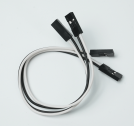
|<small>Used for quick and temporary electrical connections</small> | |||
|[[File:Jumper wires.png|frameless|134x134px]] | |||
|1 | |||
|- | |- | ||
| | |<small>29</small> | ||
| | |'''<small>Power Bank</small>''' | ||
|<small>Output</small> | |||
|<small>Battery Pack</small> | |||
|<small>Supplies portable power for uninterrupted operation.</small> | |||
|[[File:Power bank.png|frameless|138x138px]] | |||
|1 | |||
|- | |- | ||
| | |<small>30</small> | ||
|Output | |'''<small>USB Cable</small>''' | ||
|<small>Input/Output</small> | |||
|<small>Data/Charging Cable</small> | |||
|<small>Connects PeeCee to power sources and transfers data.</small> | |||
|[[File:Type C cable.png|frameless|139x139px]] | |||
|1 | |||
|} | |} | ||
== | ==Hardware== | ||
PeeCee | The PeeCee Compute Kit includes a range of plug-in sensors and actuators that expand the device's functionality. These components can be easily connected via General-Purpose Input/Output (GPIO) ports, allowing users to create complex, interactive systems. Whether it’s building a light based light shows, or a proximity-based security system, the flexibility of the PeeCee plug-in sensors opens endless possibilities for hands-on exploration and learning. By incorporating multiple sensors into a single project, users can experiment with multi-sensory input, making PeeCee an adaptable platform for more sophisticated robotics and automation projects. | ||
=== PeeCee TED : === | |||
---- | |||
From charging and input ports to interactive elements like touchpads and LEDs, knowing the anatomy of PeeCee will help you make the most out of its capabilities. Let’s dive into the details of PeeCee’s structure and how each part plays a role in your creative projects. | |||
''' | '''PeeCee Specifications :''' | ||
*'''Dual-core processor:''' Handles multiple tasks simultaneously. | *'''Dual-core processor:''' Handles multiple tasks simultaneously. | ||
*'''Wi-Fi and Bluetooth:''' Supports wireless communication and internet connectivity. | *'''Wi-Fi and Bluetooth:''' Supports wireless communication and internet connectivity. | ||
*'''Low power consumption:''' Optimized for portable, battery-powered applications. | *'''Low power consumption:''' Optimized for portable, battery-powered applications. | ||
=== | ===Other Components :=== | ||
---- | |||
==== PeeCee Shield ==== | |||
[[File:Shield 1.png|thumb|'''''PeeCee Shield''''']] | |||
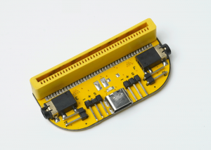
The Peecee Shield connects to the PeeCee via the edge connector, expanding the capabilities of the PeeCee Compute Kit by providing additional GPIO ports, motor and servo control, and a USB Type-C port. | |||
{| class="wikitable" | |||
!Specification | |||
!Details | |||
|- | |||
|Type | |||
|Motor shield | |||
|- | |||
|Operating voltage | |||
|5V | |||
|- | |||
|Ports | |||
|4 GPIO(E1,E2&F1,F2), | |||
2 motor ports(M1&M2), | |||
2 servo ports and | |||
a USB Type- C port (charging only) | |||
|- | |||
|Signal input /output | |||
|E&F - analog and digital | |||
M1&M2 - PWM signals | |||
Servo ports - PWM signals | |||
|- | |||
|Current rating | |||
|1.5 A (MAX) | |||
|} | |||
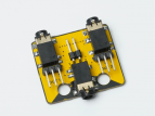
==== Motor Bridge/Splitter ==== | |||
[[File:Motor bridge.png|thumb|'''''Motor Bridge/Splitter''''']] | |||
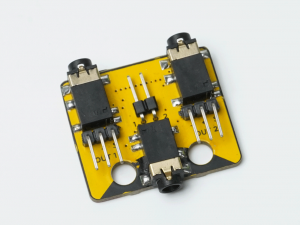
The Motor Bridge/Splitter Module expands a single GPIO port into two independent outputs (e.g., Port A to A1 and A2). It includes two servo ports and one motor port, supporting either two servos or one DC motor at a time. This module increases the versatility of the PeeCee by allowing multiple device connections through a single port. | |||
{| class="wikitable" | |||
!Specification | |||
!Details | |||
|- | |||
|Type | |||
|H-bridge/Splitter | |||
|- | |||
|Operating voltage | |||
|5V | |||
|- | |||
|Ports | |||
|2 GPIO, | |||
1 motor port and | |||
2 servo ports | |||
|- | |||
|Signal input /output | |||
|GPIO - analog and digital, Motor, | |||
Servo ports - PWM signals | |||
(Depends on which port the | |||
motor bridge is connected to) | |||
|- | |||
|Current rating | |||
|1.5 A (MAX) | |||
|} | |||
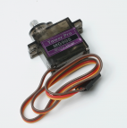
==== Servo Motor ==== | |||
[[File:Servo motor.png|thumb|232x232px|'''''Servo Motor''''']] | |||
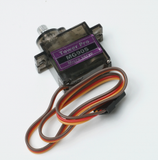
The Tower Pro MG90S Micro Servo is a high-precision, metal-geared servo motor commonly used in various electronic and robotic applications.. Known for its durability and accuracy, it provides smooth and reliable angular motion control. | |||
{| class="wikitable" | |||
!Specification | |||
!Details | |||
|- | |||
|Motor Type | |||
|MG90S (micro servo) | |||
|- | |||
|Operating voltage | |||
|4.8 V - 6.0 V | |||
|- | |||
|No load speed | |||
|100 RPM | |||
|- | |||
|Stall torque | |||
|1.8 kg.cm - 2.2kg.cm | |||
|- | |||
|Stall Current | |||
|650-800mA | |||
|} | |||
==== N20 motor ==== | |||
[[File:N20 motor.png|thumb|277x277px|'''''N2O Motor''''']] | |||
The N20 Motor is a compact, high-torque DC motor commonly used in electronic and robotic applications. Its small size and precision make it ideal for applications requiring controlled motion, such as robotic wheels, gear-driven mechanisms, and miniature automation systems. | |||
{| class="wikitable" | |||
!Specification | |||
!Details | |||
|- | |||
|Motor Type | |||
|N20 Brushed Motor | |||
|- | |||
|Operating voltage | |||
|4.8 V - 6.0 V | |||
|- | |||
|No load speed | |||
|350 RPM | |||
|- | |||
|Stall torque | |||
|0.5 kg·cm | |||
|- | |||
|Stall Current | |||
|1.2A (max) | |||
|- | |||
|No load Current | |||
|0.3A | |||
|} | |||
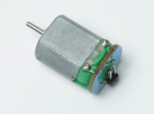
==== DC Motor ==== | |||
[[File:DC motor.png|thumb|'''''DC Motor''''']] | |||
A DC motor is an electromechanical device that converts direct current (DC) electrical energy into mechanical rotation. It is commonly used in robotics, automated systems, and motorized devices for driving wheels, gears, and actuators. Its ability to provide continuous rotation with variable speed makes it ideal for motion-based applications requiring smooth and reliable operation. | |||
{| class="wikitable" | |||
!Specification | |||
!Details | |||
|- | |||
|Motor Type | |||
|M130 DC MOTOR | |||
|- | |||
|Operating voltage | |||
|3V | |||
|- | |||
|No load Current | |||
|80-100mA | |||
|- | |||
|Stall Current | |||
|400-500mA | |||
|} | |||
==== Range Sensor ==== | |||
[[File:Range sensor 1.png|thumb|'''''Range Sensor''''']] | |||
The range sensor measures the distance between itself and an object by using infrared light. It is widely used in robotics, automation, and proximity detection applications. Range sensors are crucial for obstacle avoidance, object tracking, and environmental mapping, providing accurate measurements for real-time decision-making. | |||
{| class="wikitable" | |||
!Specification | |||
!Details | |||
|- | |||
|Sensing Technology | |||
|Infrared | |||
|- | |||
|Operating voltage | |||
|5V | |||
|- | |||
|Range | |||
|30cm (MAX) | |||
|- | |||
|Resolution | |||
|0.1cm | |||
|- | |||
|Output type | |||
|Analog | |||
|- | |||
|Response time | |||
|~ 60mS | |||
|- | |||
|Field of view | |||
|15°-20° | |||
|} | |||
==== Ultrasonic Sensor ==== | |||
[[File:Ultrasonic sensor.png|thumb|'''''Ultrasonic Sensor''''']] | |||
The ultrasonic sensor measures distances by emitting sound waves and detecting their reflection. It is widely used in robotics for obstacle detection, object avoidance, and proximity measurement. Its ease of integration and reliable performance make it ideal for autonomous navigation systems and environmental mapping. | |||
{| class="wikitable" | |||
!Specification | |||
!Details | |||
|- | |||
|Operating Current | |||
|15 mA | |||
|- | |||
|Operating voltage | |||
|5V | |||
|- | |||
|Range | |||
|255 cm | |||
|- | |||
|Accuracy | |||
|± 1% | |||
|- | |||
|Resolution | |||
|0.3cm | |||
|- | |||
|Output type | |||
|Actual distance Measured | |||
|- | |||
|Response time | |||
|~60 ms | |||
|- | |||
|Field of view | |||
|30° | |||
|} | |||
==== Potentiometer ==== | |||
[[File:POT.png|thumb|240x240px|'''''Potentiometer''''']] | |||
The potentiometer is a variable resistor used to measure or control electrical potential (voltage). It is commonly used in electronic circuits for adjusting signal levels, tuning circuits, and controlling input devices like volume knobs. | |||
{| class="wikitable" | |||
!Specification | |||
!Details | |||
|- | |||
|Resistance value | |||
|10KΩ | |||
|- | |||
|Form factor | |||
|Rotary | |||
|- | |||
|Rotation Range | |||
|270° | |||
|- | |||
|Output type | |||
|Analog | |||
|- | |||
|Tolerance | |||
|±10% | |||
|} | |||
==== Light Sensor ==== | |||
[[File:Light sensor.png|thumb|241x241px|'''''Light Sensor''''']] | |||
The light sensor detects the intensity of ambient light and converts it into an electrical signal. It is commonly used in automatic lighting systems, robots, and devices requiring light-based decision-making. With applications ranging from light-following robots to screen brightness control, light sensors provide efficient and accurate environmental monitoring. | |||
{| class="wikitable" | |||
!Specification | |||
!Details | |||
|- | |||
|Type | |||
|Resistive | |||
|- | |||
|Operating voltage | |||
|5V | |||
|- | |||
|Spectral Range | |||
|400nm - 700nm | |||
|- | |||
|Output type | |||
|Analog | |||
|- | |||
|Response time | |||
|10ms - 50ms | |||
|} | |||
==== Rain Sensor ==== | |||
[[File:Rain sensor 1.png|thumb|237x237px|'''''Rain Sensor''''']] | |||
The rain sensor detects the presence of water through conductivity changes when raindrops fall on its surface. It is often used in weather monitoring, automated windshield wipers, and smart irrigation systems. This sensor is essential for projects that respond to environmental moisture, enabling devices to detect and react to rainfall. | |||
{| class="wikitable" | |||
!Specification | |||
!Details | |||
|- | |||
|Type | |||
|Conductive | |||
|- | |||
|Operating voltage | |||
|5V | |||
|- | |||
|Output type | |||
|Analog | |||
|- | |||
|Response time | |||
|<10ms | |||
|} | |||
==== Laser Module ==== | |||
[[File:Laser module 1.png|thumb|258x258px|'''''Laser Module''''']] | |||
A laser module emits a focused beam of light, with varying wavelengths. It is widely used for positioning, object detection and optical communication. Its small size and low power consumption make it suitable for robotics, security systems, and alignment tasks where precise point projection is required. | |||
{| class="wikitable" | {| class="wikitable" | ||
! | !Specification | ||
! | !Details | ||
|- | |||
|Wavelength | |||
|650nm | |||
|- | |- | ||
| | |Operating voltage | ||
| | |5V | ||
|- | |- | ||
| | |Range | ||
| | |50-100m | ||
|- | |- | ||
| | |Output power | ||
| | |<5mW | ||
| | |- | ||
| | |Current Consumption | ||
|20-40mA | |||
|} | |||
==== Sound Card ==== | |||
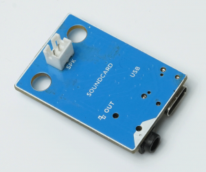
[[File:Sound card.png|thumb|'''''Sound Card''''']] | |||
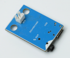
A sound card is an electronic device that processes audio signals, converting analog sound to digital data and vice versa. It is crucial for applications requiring sound output, such as speech synthesis, audio recording, and playback. It is able to support functions through simple UART serial commands | |||
{| class="wikitable" | |||
!Specification | |||
!Details | |||
|- | |||
|Audio Channels | |||
|1 channel (mono) | |||
|- | |||
|Sampling Rate | |||
|8/11.025/12/16/22.05/24/32/44.1/48 KHz | |||
|- | |||
|Bit Depth | |||
|24-bit DAC output | |||
|- | |||
|Connection Type | |||
|USB | |||
|} | |||
==== Speaker ==== | |||
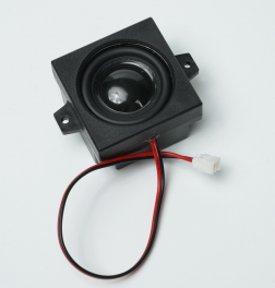
[[File:Speaker 1.png|thumb|264x264px|'''''Speaker''''']] | |||
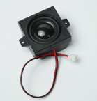
A speaker is an electroacoustic transducer that converts electrical signals into sound waves. It is used in applications requiring audio output, such as alarms, voice responses, and music playback. Speakers are essential in robotics and embedded systems for providing auditory feedback, enhancing user interaction, and enabling sound-based alerts. | |||
{| class="wikitable" | |||
!Specification | |||
!Details | |||
|- | |- | ||
| | |Power Rating | ||
| | |3W | ||
|- | |- | ||
| | |Frequency Range | ||
| | |200Hz - 20kHz | ||
|- | |- | ||
| | |Connector Type | ||
| | |2 pin JST | ||
| | |} | ||
| | |||
==== Power bank ==== | |||
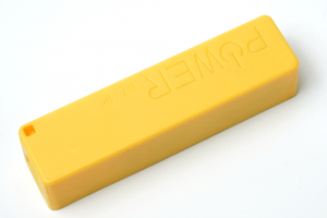
[[File:Power bank.png|thumb|'''''Powerbank''''']] | |||
Provides a stable and portable power source for the PeeCee Compute Kit and its connected components, delivering consistent voltage and current. | |||
{| class="wikitable" | |||
!Specification | |||
!Details | |||
|- | |- | ||
| | |Type | ||
| | |Lithium ion | ||
|- | |- | ||
| | |Operating voltage(USB Type-C) | ||
| | |5V | ||
|- | |- | ||
| | |Current rating | ||
| | |2.4A | ||
|- | |- | ||
| | |Power rating | ||
| | |12W | ||
|- | |- | ||
| | |Input Port | ||
| | |USB Type-C | ||
|- | |- | ||
| | |Energy | ||
|2500mAh | |||
| | |||
|} | |} | ||
== Building with PeeCee Compute Kit == | |||
=== Basic Projects === | |||
Starting with simple projects helps in understanding the components and their functionality. | |||
[[File:Disco lamp.png|thumb|299x299px|Disco Lamp]] | |||
''' | '''a. Disco lamp''' | ||
Explores RGB LED programming, creating dynamic lighting effects and interactive displays | |||
'''Key Features:''' | |||
''' | |||
* RGB Color Mixing: Understand how red, green, and blue combine to create different colors. | |||
* LED Pattern Programming: Code sequential lighting effects. | |||
* Sound Integration: Enhance visuals with buzzer-generated audio. | |||
* Hardware Connections: Connect external RGB LEDs for expanded projects. | |||
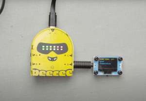
[[File:Smart Thermostat.png|thumb|Smart Thermostat]] | |||
'''b. Smart thermostat''' | |||
This process involves building a temperature meter using a temperature sensor, RGB LEDs, and an OLED display. | |||
'''Key Features:''' | |||
* Understanding Temperature Sensors: Understand how sensors measure temperature and their applications. | |||
* Visual Temperature Indicator: Use RGB LEDs to display different temperature ranges. | |||
* Real-Time Readings: Show temperature data on an OLED display for accuracy. | |||
=== Advanced Projects === | |||
After understanding the basics, more complex projects can be explored. | |||
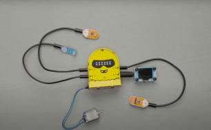
[[File:Plant Health Monitoring.png|thumb|306x306px|Plant Health Monitoring]] | |||
'''a. Plant health monitoring''' | |||
This project integrates smart sensors to develop an automated plant care solution, suitable for smart gardening and IoT applications. | |||
'' | '''Key Features:''' | ||
* Environmental Monitoring – Tracks temperature, light, and soil moisture in real time. | |||
* Automated Responses – Adjusts lighting and watering based on sensor data. | |||
* OLED Display – Shows real-time plant health metrics. | |||
* Efficient Watering System – Uses a rain sensor and motor to prevent over- or under-watering. | |||
* Hands-On Learning – Covers hardware connections, coding, and troubleshooting. | |||
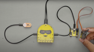
[[File:Solar align.png|thumb|303x303px|Solar align]] | |||
'''b. Solar Align''' | |||
This project integrates PeeCee with smart automation, making it an ideal learning experience for those interested in IoT, robotics, and sustainable energy solutions. | |||
'''Key Features:''' | |||
* Sunlight Detection – Uses LDR sensors to measure light intensity. | |||
* Automatic Adjustment – A servo motor repositions the solar panel for maximum energy absorption. | |||
* Hands-On Learning – Covers hardware setup, coding, and troubleshooting. | |||
* Algorithmic Control – PeeCee processes sensor data to automate movement. | |||
== Add ON's == | |||
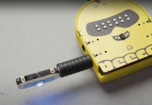
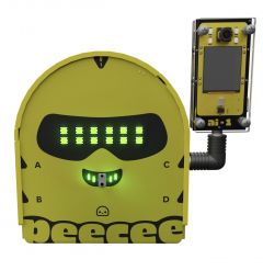
'''1. AI-cam with PeeCee:'''[[File:AI cam with Peecee.jpg|right|frameless|247x247px]]The integration of AI Cam with PeeCee enhances its capabilities by adding advanced visual processing, voice recognition, and environmental awareness. By linking the AI Cam via the port connector and managing it through the PLODE app, users can turn PeeCee into an interactive, smart assistant. | |||
'''Key Features''' | |||
* Face Recognition – Identifies and differentiates between individuals. | |||
* Voice Command Processing – Enables PeeCee to respond to spoken instructions. | |||
* Motion Detection – Detects and reacts to movement in its surroundings. | |||
This transformation elevates PeeCee from a basic computing unit to an intelligent companion capable of dynamic interactions, making it more responsive and engaging. | |||
''Visit [[AI Cam|'''AI Cam <sup>[1]</sup>''']]'' | |||
=FAQs= | =FAQs= | ||
'''1. What sensors are built into PeeCee?''' | '''1. What sensors are built into PeeCee ?''' | ||
PeeCee comes with several built-in sensors, including: | PeeCee comes with several built-in sensors, including: | ||
| Line 452: | Line 725: | ||
*Gesture sensor | *Gesture sensor | ||
*Touchpad buttons | *Touchpad buttons | ||
'''2. Can PeeCee be programmed using different languages?''' | '''2. Can PeeCee be programmed using different languages ?''' | ||
Yes, PeeCee offers a flexible programming environment, allowing users to code in multiple languages: | Yes, PeeCee offers a flexible programming environment, allowing users to code in multiple languages: | ||
| Line 460: | Line 733: | ||
*Python Programming (For advanced users) | *Python Programming (For advanced users) | ||
*C Programming (For advanced users) | *C Programming (For advanced users) | ||
'''3. What devices can I connect to PeeCee’s GPIO ports?''' | '''3. What devices can I connect to PeeCee’s GPIO ports ?''' | ||
PeeCee has four GPIO ports (A, B, C, D) that allow you to connect various external devices like infrared sensors, ultrasonic sensors, potentiometers, motors, and more. These can be used to build more advanced robotics and automation projects. | PeeCee has four GPIO ports (A, B, C, D) that allow you to connect various external devices like infrared sensors, ultrasonic sensors, potentiometers, motors, and more. These can be used to build more advanced robotics and automation projects. | ||
4. How do I control and program PeeCee? | '''4. How do I control and program PeeCee ?''' | ||
PeeCee is controlled and programmed through the PLODE app, which offers multiple coding methods, including block programming, Python, and C. The app can be accessed on both the web and mobile devices, making it easy to manage your projects on the go. | PeeCee is controlled and programmed through the PLODE app, which offers multiple coding methods, including block programming, Python, and C. The app can be accessed on both the web and mobile devices, making it easy to manage your projects on the go. | ||
'''5. How does the AI Cam integrate with PeeCee?''' | '''5. How does the AI Cam integrate with PeeCee ?''' | ||
The AI Cam connects via an auxiliary connector and adds features like facial recognition, voice commands, and motion detection. This allows PeeCee to become an interactive, smart assistant with advanced environmental awareness. | The AI Cam connects via an auxiliary connector and adds features like facial recognition, voice commands, and motion detection. This allows PeeCee to become an interactive, smart assistant with advanced environmental awareness. | ||
'''6. Is PeeCee compatible with building blocks like LEGO?''' | '''6. Is PeeCee compatible with building blocks like LEGO ?''' | ||
Yes, PeeCee is designed to be compatible with physical building blocks, allowing users to create structures and systems that combine coding with physical construction. | Yes, PeeCee is designed to be compatible with physical building blocks, allowing users to create structures and systems that combine coding with physical construction. | ||
| Line 496: | Line 769: | ||
'''8. How do I erase a program on PeeCee?''' | '''8. How do I erase a program on PeeCee?''' | ||
To erase a program on PeeCee, you can double-tap the button on the | To erase a program on PeeCee, you can double-tap the button on the side of PeeCee. RGBeyes will turn red indicating that the program has been reset. A long press of the power button will turn off the device. | ||
'''9. Can PeeCee be used for AI projects?''' | '''9. Can PeeCee be used for AI projects?''' | ||
Yes, with the integration of the AI Cam, PeeCee can be used for AI-related projects like face recognition, voice commands, and motion detection, making it suitable for interactive and intelligent robotics. | Yes, with the integration of the AI Cam, PeeCee can be used for AI-related projects like face recognition, voice commands, and motion detection, making it suitable for interactive and intelligent robotics. | ||
Latest revision as of 17:26, 3 April 2025
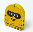
The PeeCee Compute Kit is your ultimate companion for diving into educational robotics or hands-on learning in STEM with style and precision. Designed for schools, institutions, and anyone passionate about STEM, this versatile kit combines the powerhouse PeeCee TED with an array of components like sensors, motors, and servos to create a complete robotics playground. PeeCee TED itself is an advanced iot and measurement device, making it perfect for projects that demand accuracy and adaptability.
Whether you are experimenting with sensors, programming motorized robots, or measuring environmental parameters, the Compute Kit offers endless possibilities for innovation. Fully compatible with the PLODE platform, it empowers students and educators to easily code and simulate projects, ensuring a seamless learning experience. Built to last, the PeeCee Compute Kit is ideal for repeated use, making it a smart investment for classrooms, makerspaces, and robotics clubs. It fosters hands-on learning by encouraging creativity, logical thinking, and problem-solving skills. From crafting robots that bring imaginative ideas to life to tackling complex engineering challenges, this kit is a gateway to mastering robotics from the basics to the advanced.
If you are looking for a reusable, adaptable, and educational robotics solution, PeeCee Compute Kit is where your search ends. It is not just a kit—it is a toolkit for the future of learning, designed to inspire and nurture the innovators of tomorrow.
Overview
Welcome to PeeCee, your gateway to turning big ideas into awesome robotic creations. The PeeCee Compute Kit combines hardware and software to enable users to design interactive systems. Its core component, the PeeCee TED unit, supports connectivity with various plug-in sensors and actuators via General-Purpose Input/Output (GPIO) ports.
The kit integrates with the PLODE platform, which offers coding and simulation capabilities in multiple programming languages, including block-based coding, Python, and C, that make this kit a tech playground. Applications include real-time environmental monitoring, precise motion control, and multi-sensory robotics projects.
What's Inside the Box:
Open the box of the PeeCee Compute Kit and step into a world of endless possibilities. Designed for creative minds and curious learners, this kit equips you with all the tools needed to explore the realms of robotics and technology. Dive into hands-on learning and build, code, and innovate with ease. The PeeCee Compute Kit comes with everything you need to begin your journey, offering a solid foundation for all your STEM explorations.
The kit comprises the following components:
Hardware
The PeeCee Compute Kit includes a range of plug-in sensors and actuators that expand the device's functionality. These components can be easily connected via General-Purpose Input/Output (GPIO) ports, allowing users to create complex, interactive systems. Whether it’s building a light based light shows, or a proximity-based security system, the flexibility of the PeeCee plug-in sensors opens endless possibilities for hands-on exploration and learning. By incorporating multiple sensors into a single project, users can experiment with multi-sensory input, making PeeCee an adaptable platform for more sophisticated robotics and automation projects.
PeeCee TED :
From charging and input ports to interactive elements like touchpads and LEDs, knowing the anatomy of PeeCee will help you make the most out of its capabilities. Let’s dive into the details of PeeCee’s structure and how each part plays a role in your creative projects.
PeeCee Specifications :
- Dual-core processor: Handles multiple tasks simultaneously.
- Wi-Fi and Bluetooth: Supports wireless communication and internet connectivity.
- Low power consumption: Optimized for portable, battery-powered applications.
Other Components :
PeeCee Shield
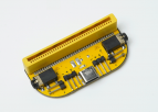
The Peecee Shield connects to the PeeCee via the edge connector, expanding the capabilities of the PeeCee Compute Kit by providing additional GPIO ports, motor and servo control, and a USB Type-C port.
| Specification | Details |
|---|---|
| Type | Motor shield |
| Operating voltage | 5V |
| Ports | 4 GPIO(E1,E2&F1,F2),
2 motor ports(M1&M2), 2 servo ports and a USB Type- C port (charging only) |
| Signal input /output | E&F - analog and digital
M1&M2 - PWM signals Servo ports - PWM signals |
| Current rating | 1.5 A (MAX) |
Motor Bridge/Splitter
The Motor Bridge/Splitter Module expands a single GPIO port into two independent outputs (e.g., Port A to A1 and A2). It includes two servo ports and one motor port, supporting either two servos or one DC motor at a time. This module increases the versatility of the PeeCee by allowing multiple device connections through a single port.
| Specification | Details |
|---|---|
| Type | H-bridge/Splitter |
| Operating voltage | 5V |
| Ports | 2 GPIO,
1 motor port and 2 servo ports |
| Signal input /output | GPIO - analog and digital, Motor,
Servo ports - PWM signals (Depends on which port the motor bridge is connected to) |
| Current rating | 1.5 A (MAX) |
Servo Motor
The Tower Pro MG90S Micro Servo is a high-precision, metal-geared servo motor commonly used in various electronic and robotic applications.. Known for its durability and accuracy, it provides smooth and reliable angular motion control.
| Specification | Details |
|---|---|
| Motor Type | MG90S (micro servo) |
| Operating voltage | 4.8 V - 6.0 V |
| No load speed | 100 RPM |
| Stall torque | 1.8 kg.cm - 2.2kg.cm |
| Stall Current | 650-800mA |
N20 motor
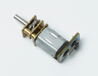
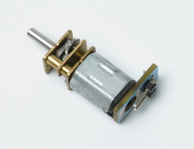
The N20 Motor is a compact, high-torque DC motor commonly used in electronic and robotic applications. Its small size and precision make it ideal for applications requiring controlled motion, such as robotic wheels, gear-driven mechanisms, and miniature automation systems.
| Specification | Details |
|---|---|
| Motor Type | N20 Brushed Motor |
| Operating voltage | 4.8 V - 6.0 V |
| No load speed | 350 RPM |
| Stall torque | 0.5 kg·cm |
| Stall Current | 1.2A (max) |
| No load Current | 0.3A |
DC Motor
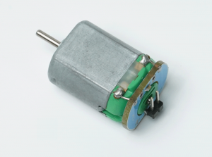
A DC motor is an electromechanical device that converts direct current (DC) electrical energy into mechanical rotation. It is commonly used in robotics, automated systems, and motorized devices for driving wheels, gears, and actuators. Its ability to provide continuous rotation with variable speed makes it ideal for motion-based applications requiring smooth and reliable operation.
| Specification | Details |
|---|---|
| Motor Type | M130 DC MOTOR |
| Operating voltage | 3V |
| No load Current | 80-100mA |
| Stall Current | 400-500mA |
Range Sensor
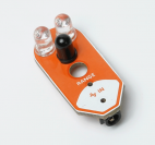
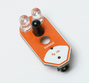
The range sensor measures the distance between itself and an object by using infrared light. It is widely used in robotics, automation, and proximity detection applications. Range sensors are crucial for obstacle avoidance, object tracking, and environmental mapping, providing accurate measurements for real-time decision-making.
| Specification | Details |
|---|---|
| Sensing Technology | Infrared |
| Operating voltage | 5V |
| Range | 30cm (MAX) |
| Resolution | 0.1cm |
| Output type | Analog |
| Response time | ~ 60mS |
| Field of view | 15°-20° |
Ultrasonic Sensor
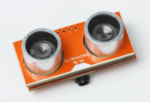
The ultrasonic sensor measures distances by emitting sound waves and detecting their reflection. It is widely used in robotics for obstacle detection, object avoidance, and proximity measurement. Its ease of integration and reliable performance make it ideal for autonomous navigation systems and environmental mapping.
| Specification | Details |
|---|---|
| Operating Current | 15 mA |
| Operating voltage | 5V |
| Range | 255 cm |
| Accuracy | ± 1% |
| Resolution | 0.3cm |
| Output type | Actual distance Measured |
| Response time | ~60 ms |
| Field of view | 30° |
Potentiometer
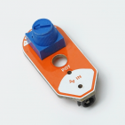
The potentiometer is a variable resistor used to measure or control electrical potential (voltage). It is commonly used in electronic circuits for adjusting signal levels, tuning circuits, and controlling input devices like volume knobs.
| Specification | Details |
|---|---|
| Resistance value | 10KΩ |
| Form factor | Rotary |
| Rotation Range | 270° |
| Output type | Analog |
| Tolerance | ±10% |
Light Sensor
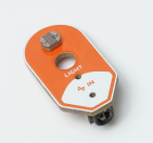
The light sensor detects the intensity of ambient light and converts it into an electrical signal. It is commonly used in automatic lighting systems, robots, and devices requiring light-based decision-making. With applications ranging from light-following robots to screen brightness control, light sensors provide efficient and accurate environmental monitoring.
| Specification | Details |
|---|---|
| Type | Resistive |
| Operating voltage | 5V |
| Spectral Range | 400nm - 700nm |
| Output type | Analog |
| Response time | 10ms - 50ms |
Rain Sensor
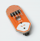
The rain sensor detects the presence of water through conductivity changes when raindrops fall on its surface. It is often used in weather monitoring, automated windshield wipers, and smart irrigation systems. This sensor is essential for projects that respond to environmental moisture, enabling devices to detect and react to rainfall.
| Specification | Details |
|---|---|
| Type | Conductive |
| Operating voltage | 5V |
| Output type | Analog |
| Response time | <10ms |
Laser Module
A laser module emits a focused beam of light, with varying wavelengths. It is widely used for positioning, object detection and optical communication. Its small size and low power consumption make it suitable for robotics, security systems, and alignment tasks where precise point projection is required.
| Specification | Details |
|---|---|
| Wavelength | 650nm |
| Operating voltage | 5V |
| Range | 50-100m |
| Output power | <5mW |
| Current Consumption | 20-40mA |
Sound Card
A sound card is an electronic device that processes audio signals, converting analog sound to digital data and vice versa. It is crucial for applications requiring sound output, such as speech synthesis, audio recording, and playback. It is able to support functions through simple UART serial commands
| Specification | Details |
|---|---|
| Audio Channels | 1 channel (mono) |
| Sampling Rate | 8/11.025/12/16/22.05/24/32/44.1/48 KHz |
| Bit Depth | 24-bit DAC output |
| Connection Type | USB |
Speaker
A speaker is an electroacoustic transducer that converts electrical signals into sound waves. It is used in applications requiring audio output, such as alarms, voice responses, and music playback. Speakers are essential in robotics and embedded systems for providing auditory feedback, enhancing user interaction, and enabling sound-based alerts.
| Specification | Details |
|---|---|
| Power Rating | 3W |
| Frequency Range | 200Hz - 20kHz |
| Connector Type | 2 pin JST |
Power bank
Provides a stable and portable power source for the PeeCee Compute Kit and its connected components, delivering consistent voltage and current.
| Specification | Details |
|---|---|
| Type | Lithium ion |
| Operating voltage(USB Type-C) | 5V |
| Current rating | 2.4A |
| Power rating | 12W |
| Input Port | USB Type-C |
| Energy | 2500mAh |
Building with PeeCee Compute Kit
Basic Projects
Starting with simple projects helps in understanding the components and their functionality.
a. Disco lamp
Explores RGB LED programming, creating dynamic lighting effects and interactive displays
Key Features:
- RGB Color Mixing: Understand how red, green, and blue combine to create different colors.
- LED Pattern Programming: Code sequential lighting effects.
- Sound Integration: Enhance visuals with buzzer-generated audio.
- Hardware Connections: Connect external RGB LEDs for expanded projects.
b. Smart thermostat
This process involves building a temperature meter using a temperature sensor, RGB LEDs, and an OLED display.
Key Features:
- Understanding Temperature Sensors: Understand how sensors measure temperature and their applications.
- Visual Temperature Indicator: Use RGB LEDs to display different temperature ranges.
- Real-Time Readings: Show temperature data on an OLED display for accuracy.
Advanced Projects
After understanding the basics, more complex projects can be explored.
a. Plant health monitoring
This project integrates smart sensors to develop an automated plant care solution, suitable for smart gardening and IoT applications.
Key Features:
- Environmental Monitoring – Tracks temperature, light, and soil moisture in real time.
- Automated Responses – Adjusts lighting and watering based on sensor data.
- OLED Display – Shows real-time plant health metrics.
- Efficient Watering System – Uses a rain sensor and motor to prevent over- or under-watering.
- Hands-On Learning – Covers hardware connections, coding, and troubleshooting.
b. Solar Align
This project integrates PeeCee with smart automation, making it an ideal learning experience for those interested in IoT, robotics, and sustainable energy solutions.
Key Features:
- Sunlight Detection – Uses LDR sensors to measure light intensity.
- Automatic Adjustment – A servo motor repositions the solar panel for maximum energy absorption.
- Hands-On Learning – Covers hardware setup, coding, and troubleshooting.
- Algorithmic Control – PeeCee processes sensor data to automate movement.
Add ON's
1. AI-cam with PeeCee:
The integration of AI Cam with PeeCee enhances its capabilities by adding advanced visual processing, voice recognition, and environmental awareness. By linking the AI Cam via the port connector and managing it through the PLODE app, users can turn PeeCee into an interactive, smart assistant.
Key Features
- Face Recognition – Identifies and differentiates between individuals.
- Voice Command Processing – Enables PeeCee to respond to spoken instructions.
- Motion Detection – Detects and reacts to movement in its surroundings.
This transformation elevates PeeCee from a basic computing unit to an intelligent companion capable of dynamic interactions, making it more responsive and engaging.
Visit AI Cam [1]
FAQs
1. What sensors are built into PeeCee ?
PeeCee comes with several built-in sensors, including:
- Microphone (sound detection)
- Temperature sensor
- Accelerometer (3-axis)
- Gyroscope (3-axis)
- Color sensor (RGB intensity)
- Light sensor
- Distance sensor (ultrasonic)
- Gesture sensor
- Touchpad buttons
2. Can PeeCee be programmed using different languages ?
Yes, PeeCee offers a flexible programming environment, allowing users to code in multiple languages:
- Hex Block Programming (Beginner-friendly)
- Block Programming (Similar to Scratch)
- Flowchart Programming (Visual logic design)
- Python Programming (For advanced users)
- C Programming (For advanced users)
3. What devices can I connect to PeeCee’s GPIO ports ?
PeeCee has four GPIO ports (A, B, C, D) that allow you to connect various external devices like infrared sensors, ultrasonic sensors, potentiometers, motors, and more. These can be used to build more advanced robotics and automation projects.
4. How do I control and program PeeCee ?
PeeCee is controlled and programmed through the PLODE app, which offers multiple coding methods, including block programming, Python, and C. The app can be accessed on both the web and mobile devices, making it easy to manage your projects on the go.
5. How does the AI Cam integrate with PeeCee ?
The AI Cam connects via an auxiliary connector and adds features like facial recognition, voice commands, and motion detection. This allows PeeCee to become an interactive, smart assistant with advanced environmental awareness.
6. Is PeeCee compatible with building blocks like LEGO ?
Yes, PeeCee is designed to be compatible with physical building blocks, allowing users to create structures and systems that combine coding with physical construction.
7. What’s included in the PeeCee box?
The PeeCee box includes:
- 1 PeeCee unit
- Infrared Sensor
- Ultrasonic Sensor
- Potentiometer
- Light-Dependent Resistor (LDR)
- Rain Sensor
- Servo Motor
- DC Motor
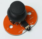
- Joystick
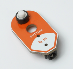
- Push Button
- LED, LED 2C
- DIP Switch
- Laser Module
- Speaker
- Cables and connectors
8. How do I erase a program on PeeCee?
To erase a program on PeeCee, you can double-tap the button on the side of PeeCee. RGBeyes will turn red indicating that the program has been reset. A long press of the power button will turn off the device.
9. Can PeeCee be used for AI projects?
Yes, with the integration of the AI Cam, PeeCee can be used for AI-related projects like face recognition, voice commands, and motion detection, making it suitable for interactive and intelligent robotics.
