Playtronix: Difference between revisions
Evobi admin (talk | contribs) No edit summary |
Evobi admin (talk | contribs) mNo edit summary |
||
| Line 32: | Line 32: | ||
|Supplies power to the entire circuit | |Supplies power to the entire circuit | ||
| | | | ||
|[[File:Power | |[[File:Power .jpg|129x129px]] | ||
|- | |- | ||
|2 | |2 | ||
| Line 41: | Line 41: | ||
|Detects light levels and changes resistance accordingly | |Detects light levels and changes resistance accordingly | ||
| | | | ||
|[[File: | |[[File:LDR module.jpg|129x129px]] | ||
|- | |- | ||
|3 | |3 | ||
| Line 51: | Line 51: | ||
|A push-button switch for temporary on/off contro | |A push-button switch for temporary on/off contro | ||
| | | | ||
|[[File: | |[[File:Tact .jpg|129x129px]] | ||
|- | |- | ||
|4 | |4 | ||
| Line 60: | Line 60: | ||
|Directs current along two possible paths | |Directs current along two possible paths | ||
| | | | ||
|[[File: | |[[File:Two way switch.jpg|129x129px]] | ||
|- | |- | ||
|5 | |5 | ||
| Line 70: | Line 70: | ||
|Multiple switches in one package for mode selection | |Multiple switches in one package for mode selection | ||
| | | | ||
|[[File: | |[[File:Dip.jpg|129x129px]] | ||
|- | |- | ||
|6 | |6 | ||
| Line 79: | Line 79: | ||
|A twistable knob to adjust resistance | |A twistable knob to adjust resistance | ||
| | | | ||
|[[File: | |[[File:POT module.jpg|132x132px]] | ||
|- | |- | ||
|7 | |7 | ||
| Line 88: | Line 88: | ||
| Lights up when current flows through it | | Lights up when current flows through it | ||
| | | | ||
|[[File: | |[[File:LED.jpg|129x129px]] | ||
|- | |- | ||
|8 | |8 | ||
| Line 97: | Line 97: | ||
|Lights up in various colors depending on input | |Lights up in various colors depending on input | ||
| | | | ||
|[[File: | |[[File:RGB Led.png|129x129px]] | ||
|- | |- | ||
| 9 | | 9 | ||
| Line 106: | Line 106: | ||
|Emits a tone or beep when powered | |Emits a tone or beep when powered | ||
| | | | ||
|[[File: | |[[File:Beeper module.jpg|129x129px]] | ||
|- | |- | ||
|10 | |10 | ||
| Line 115: | Line 115: | ||
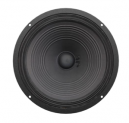
|Converts signals into sound | |Converts signals into sound | ||
| | | | ||
|[[File: | |[[File:Speaker module.png|129x129px]] | ||
|- | |- | ||
|11 | |11 | ||
| Line 124: | Line 124: | ||
|Spins when powered to enable motion | |Spins when powered to enable motion | ||
| | | | ||
|[[File: | |[[File:DC Motor module.png|132x132px]] | ||
|- | |- | ||
|12 | |12 | ||
| Line 132: | Line 132: | ||
|Limits or divides electric current | |Limits or divides electric current | ||
| | | | ||
|[[File: | |[[File:Resistor.jpg|129x129px]] | ||
|- | |- | ||
|13 | |13 | ||
| Line 140: | Line 140: | ||
|Stores and releases electrical energy | |Stores and releases electrical energy | ||
| | | | ||
|[[File: | |[[File:Capacitor.jpg|129x129px]] | ||
|- | |- | ||
|14 | |14 | ||
| Line 148: | Line 148: | ||
|Allows current to flow in one direction only | |Allows current to flow in one direction only | ||
| | | | ||
|[[File: | |[[File:Diode.jpg|129x129px]] | ||
|- | |- | ||
|15 | |15 | ||
| Line 156: | Line 156: | ||
|Amplifies or switches electronic signals | |Amplifies or switches electronic signals | ||
| | | | ||
| [[File: | | [[File:Transisitor.jpg|129x129px]] | ||
|- | |- | ||
|16 | |16 | ||
| Line 164: | Line 164: | ||
|Generates timed pulses or oscillations in circuits | |Generates timed pulses or oscillations in circuits | ||
| | | | ||
| [[File: | | [[File:Timer.jpg|129x129px]] | ||
|- | |- | ||
|17 | |17 | ||
| Line 172: | Line 172: | ||
|Connects multiple components at a single point | |Connects multiple components at a single point | ||
| | | | ||
|[[File: | |[[File:Junction module.jpg|134x134px]] | ||
|- | |- | ||
|18 | |18 | ||
| Line 180: | Line 180: | ||
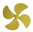
|Spins when attached to a motor to create airflow | |Spins when attached to a motor to create airflow | ||
| | | | ||
|[[File: | |[[File:Propeller .png|129x129px]] | ||
|- | |- | ||
|19 | |19 | ||
| Line 188: | Line 188: | ||
|Conductors | |Conductors | ||
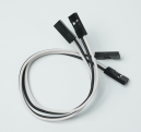
|Bridges connections between components for circuit flow | |Bridges connections between components for circuit flow | ||
| | | | ||
|[[File:Jumper wires.png|129x129px]] | |[[File:Jumper wires.png|129x129px]] | ||
|} | |} | ||
=== Input Components === | === Input Components === | ||
Revision as of 16:06, 17 June 2025
Playtronix
The Playtronix Kit is your all-access pass to the world of electronics, built for curious minds ready to dive into circuits, components, and all the magic that makes gadgets tick. Designed with beginners in mind, this educational kit takes the mystery out of electricity through fun, hands-on projects. Whether you're lighting up an LED or triggering a buzzer with a button, Playtronix makes electronics engaging, accessible, and—most importantly—exciting. Ideal for classrooms, STEM labs, or home experimentation, it lays the perfect foundation for anyone looking to understand how everyday electronics actually work.
Key Features
Foundation for Electronics Learning: Designed to teach the basics of electronics through real-world experimentation and observation.
Beginner-Friendly Components: All parts are labeled clearly, with simplified connectors and color-coded elements.
Step-by-Step Manual: Comes with a detailed guidebook covering components, circuit diagrams, and how-tos.
Encourages Exploration: Students can go beyond the basics and combine components to create their own unique circuits.
Reusable and Versatile: Durable kit contents designed to support many hours of tinkering, learning, and inventing.
What’s in the Kit?
Open the box of the Playtrons Kit and let the adventure begin! Designed for young thinkers and little tinkerers, this kit is the perfect introduction to the world of electronics and STEM. With easy-to-use components and no coding required, kids can jump right into building simple circuits and exploring how things work—all through hands-on play. The Playtrons Kit comes with everything needed to spark imagination and curiosity, laying a fun and solid foundation for early tech learning.
Input Components
These components take signals from the outside world and send them into your circuit.
LDR: Detects light levels and changes resistance accordingly.
Tactile Switch: A push-button switch for temporary connections.
Two-Way Switch: Directs current along two possible paths.
DIP Switch: Multiple mini-switches in one—great for setting modes or options.
Potentiometer: A twistable knob that changes resistance values.
Output Components
These turn circuit signals into visible or audible results.
LED: Lights up when current flows through it.
RGB LED: Glows in different colors depending on input.
Beeper: Emits a tone or beep when powered.
Speaker: Converts signals into sound—perfect for audio-based projects.
DC Motor: Spins when powered, making it ideal for movement-based builds.
Other Components
These tie everything together and enable more complex functionality.
Power Module
Resistors
Capacitors
Diodes
Transistors
Timer IC (e.g., 555 timer)
Junctions
Propeller
Connecting Wires / Jumper Cables
Component Descriptions
LDR
A light-dependent resistor (LDR) changes its resistance based on the amount of light it receives. Bright light lowers resistance, while darkness increases it. Often used in automatic night lights and solar garden lamps.
Tactile Switch
A momentary push-button switch that closes the circuit only when pressed. Found in calculators, reset buttons, and game controllers.
Two-Way Switch
Routes current to one of two output paths. Common in stairway lighting systems and dual-mode electronic projects.
DIP Switch
A compact group of toggle switches used to configure a circuit manually. Often used to set device IDs or behavior without software.
Potentiometer
A variable resistor controlled by turning a knob. Used in volume controls, brightness settings, or tuning circuits.
LED
Lights up when powered. Comes in various colors and sizes. Super efficient and great for indicators.
RGB LED
A single LED that combines red, green, and blue light to produce different colors. Can be used for decorative lighting or status indicators.
Beeper
Generates simple sound cues. Excellent for alarms, error notifications, or simple sound effects.
Speaker
Converts electrical signals into sound. Can be used for music, voices, or custom tones.
DC Motor
Converts electrical energy into mechanical rotation. Attach a propeller and you've got a fan; add wheels, and it's a vehicle.
Propeller
A plastic fan blade that connects to a DC motor. Helps visualize motor action and explore airflow-based projects.
Resistors
Control how much current flows through a circuit. Identified by colorful bands which indicate their resistance value.
Capacitors
Store electrical energy and release it when needed. Often used in timing circuits, filters, and power supplies.
Diodes
Allow current to flow in only one direction. Useful for protection circuits and AC-to-DC conversion.
Transistors
Small but mighty! These components amplify signals or act as electronic switches.
Timer IC
Often the 555 timer, these chips can generate precise timing pulses. Used in blinkers, delays, and waveform generators.
Junction
Connection points where wires or components meet—like an intersection in a circuit.
Power Module
Distributes power to all parts of your project. Often includes on/off switches and voltage regulators.
Jumper Cables
Flexible wires used to link different parts of a circuit. Great for breadboarding and experimenting.


