Playtrons: Difference between revisions
Evobi admin (talk | contribs) No edit summary |
Evobi admin (talk | contribs) |
||
| (2 intermediate revisions by the same user not shown) | |||
| Line 206: | Line 206: | ||
== 1. Power module == | == 1. Power module == | ||
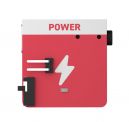
The power module | The power module serves as the central unit in any project, distributing power to all connected components. It regulates voltage to ensure stability and safety during operation. This allows users, especially beginners, to engage in experimentation without concerns about electrical safety. Simply connect the module to initiate the project, providing a reliable foundation for various electrical activities | ||
[[File:Tact switch.jpg|thumb|180x180px|Tact Switch]] | [[File:Tact switch.jpg|thumb|180x180px|Tact Switch]] | ||
== 2. Tact Switch == | == 2. Tact Switch == | ||
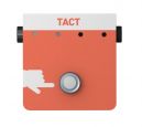
This | This button is a component that sends a signal only when pressed, making it ideal for triggering actions such as illuminating an LED or activating a sound. This button is particularly useful for introducing users, especially beginners, to momentary input controls. Upon pressing, it initiates a brief response, enabling users to explore interactive electronic projects and their behavior. | ||
[[File:Switch 3.jpg|thumb|180x180px|Switch]] | [[File:Switch 3.jpg|thumb|180x180px|Switch]] | ||
| Line 228: | Line 222: | ||
== 3. Switch == | == 3. Switch == | ||
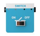
The toggle switch maintains a persistent state (on or off) until manually flipped to the opposite position. It is designed to teach users about stable states in electrical circuits. This switch is ideal for implementing simple on/off functions and power control in basic electronic projects, providing an introduction to more advanced concepts of circuit behavior and control mechanisms. | |||
[[File:LED module.jpg|thumb|180x180px|LED Module]] | [[File:LED module.jpg|thumb|180x180px|LED Module]] | ||
| Line 242: | Line 233: | ||
== 4. LED == | == 4. LED == | ||
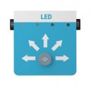
The LED | The LED illuminates when supplied with power, providing a clear visual representation of electrical flow. It is commonly used as an indicator or alert in various electronic circuits. Safe and easy to use, the LED offers an engaging way for beginners to experiment with visual feedback mechanisms, enhancing their understanding of electrical concepts in hands-on projects. | ||
[[File:Junction Module.jpg|thumb|180x180px|Junction Module]] | [[File:Junction Module.jpg|thumb|180x180px|Junction Module]] | ||
| Line 254: | Line 243: | ||
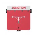
== 5. Junction == | == 5. Junction == | ||
The junction is | The junction is a connection point where multiple wires or components can converge, enabling more complex circuit designs. It facilitates the control of several outputs from a single input, streamlining circuit connections. Commonly used in applications requiring signal distribution, the junction acts as a central node, allowing multiple pathways for electrical signals to flow simultaneously within a system. | ||
[[File:Beeper Module.jpg|thumb|180x180px|Beeper Module]] | [[File:Beeper Module.jpg|thumb|180x180px|Beeper Module]] | ||
| Line 265: | Line 251: | ||
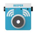
== 6. Beeper == | == 6. Beeper == | ||
The buzzer is an electronic component that produces sound when activated, commonly used for alerts or interactive feedback in circuits. It provides auditory responses to various events, enhancing the user experience in electronic projects. Often employed in systems requiring audio signals, such as alarms or notifications, the buzzer adds dynamic audio cues, increasing the engagement and interactivity of the project. | |||
[[File:Counter Module .jpg|thumb|180x180px|Counter Module ]] | [[File:Counter Module .jpg|thumb|180x180px|Counter Module ]] | ||
| Line 278: | Line 260: | ||
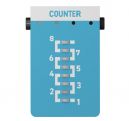
== 7. Counter == | == 7. Counter == | ||
The counter | The counter is an electronic component designed to track the number of occurrences of an event, such as a button press or sensor activation. It is commonly used to demonstrate basic event tracking and memory functionality in electronics. This component allows users to measure and record the frequency of specific actions, enabling the study of behavior patterns over time in various applications. | ||
[[File:Graph Module 1.jpg|thumb|180x180px|Graph Module]] | [[File:Graph Module 1.jpg|thumb|180x180px|Graph Module]] | ||
| Line 292: | Line 271: | ||
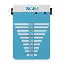
== 8. Graph == | == 8. Graph == | ||
The graph module visually | The graph module is a component that visually represents sensor data, such as temperature, light, or proximity, in a simplified format. It allows users, particularly beginners, to observe and interpret changes in real-time without the need for a screen. This tool serves as an introductory method for understanding data visualization, making it an effective learning aid for basic sensor-based projects. | ||
[[File:Greater than Module.jpg|thumb|180x180px|Greater than Module]] | [[File:Greater than Module.jpg|thumb|180x180px|Greater than Module]] | ||
| Line 304: | Line 281: | ||
== 9. Greater Than Condition Module == | == 9. Greater Than Condition Module == | ||
This smart module | This smart module is designed to activate an output when a sensor reading exceeds a predefined threshold value. It introduces logical comparisons, such as "if the temperature exceeds 30°C, turn on the fan," enabling users to implement conditional actions. This module provides an engaging way to teach basic logic and sensor-driven control, offering an introductory experience to decision-making in electronic systems. | ||
[[File:Less Than Module.jpg|thumb|180x180px|Less than Module]] | [[File:Less Than Module.jpg|thumb|180x180px|Less than Module]] | ||
| Line 317: | Line 290: | ||
== 10. Less Than Condition Module == | == 10. Less Than Condition Module == | ||
The | The less-than module triggers an output when a sensor reading falls below a specified threshold. It is commonly used in applications such as "if it's dark, turn on the light." This module facilitates the understanding of rule-based logic and critical thinking, offering an opportunity to implement conditional actions based on environmental conditions, making it ideal for sensor-based projects. | ||
[[File:Light sensor 1.jpg|thumb|180x180px|Light Sensor]] | |||
| Line 329: | Line 300: | ||
== 11. Light Sensor == | == 11. Light Sensor == | ||
The light sensor detects ambient brightness levels and enables the creation of light-activated projects, such as automatic nightlights. It allows users to explore how electronic devices can respond to environmental changes, similar to how eyes detect light. This sensor is particularly useful in teaching fundamental concepts of environmental interaction and sensor-based automation in electronic circuits. | |||
[[File:Temperature Sensor 2.jpg|thumb|180x180px|Temperature sensor]] | |||
| Line 341: | Line 310: | ||
== 12. Temperature Sensor == | == 12. Temperature Sensor == | ||
The temperature sensor measures heat levels, enabling the creation of temperature-sensitive projects. It can be utilized in a variety of applications, such as triggering devices like fans or buzzers based on temperature changes. This sensor provides an interactive learning experience, helping users understand thermal concepts and their practical applications in electronics and automation systems. | |||
[[File:Magnetic Sensor 2.jpg|alt=Magnetic Sensor|thumb|180x180px|Magnetic Sensor]] | [[File:Magnetic Sensor 2.jpg|alt=Magnetic Sensor|thumb|180x180px|Magnetic Sensor]] | ||
| Line 353: | Line 319: | ||
== 13. Magnetic Sensor == | == 13. Magnetic Sensor == | ||
The magnetic sensor is a component that detects the presence of magnets or magnetic fields. It is commonly used in applications requiring invisible triggers or concealed switches. This sensor is ideal for interactive projects, such as games or hidden circuits, where magnetic fields are used to unlock or activate certain actions, providing an innovative way to incorporate magnetism into electronic designs. | |||
[[File:Proximity Sensor.jpg|thumb|180x180px|Proximity Sensor]] | [[File:Proximity Sensor.jpg|thumb|180x180px|Proximity Sensor]] | ||
| Line 364: | Line 328: | ||
== 14. Proximity Sensor == | == 14. Proximity Sensor == | ||
The proximity sensor detects | The proximity sensor detects the presence of objects within a specified range without physical contact. It provides spatial awareness to a project, enabling it to respond to nearby movements. Commonly used in applications such as motion-activated lights, alarms, or distance-based actions, the proximity sensor offers an interactive way to integrate responsive behaviors in electronic systems and projects. | ||
[[File:Motor Module 1.jpg|thumb|180x180px|Motor Module]] | [[File:Motor Module 1.jpg|thumb|180x180px|Motor Module]] | ||
| Line 376: | Line 339: | ||
== 15. Motor Module == | == 15. Motor Module == | ||
The motor control module regulates and powers a motor, allowing control over speed and direction. It is used to convert electrical signals into mechanical motion, enabling tasks such as spinning a propeller. This module serves as an introduction to robotics and movement control, providing essential functionality for building dynamic, motor-driven projects. | |||
[[File:DC Motor .jpg|thumb|180x180px|DC Motor]] | [[File:DC Motor .jpg|thumb|180x180px|DC Motor]] | ||
| Line 391: | Line 350: | ||
== 16. Motor == | == 16. Motor == | ||
Once connected, | The motor converts electrical energy into mechanical motion, enabling movement in projects. Once connected, it initiates rotation, powering devices such as fans, spinners, or simple vehicles. This component is essential for introducing users to basic principles of energy conversion, demonstrating how electrical signals can drive motion in various mechanical applications, making it a key element in hands-on engineering projects. | ||
| Line 404: | Line 361: | ||
== 17. Propellor == | == 17. Propellor == | ||
The propeller, when attached to a motor, converts rotational motion into airflow, demonstrating how mechanical movement can produce tangible effects, such as moving air or cooling objects. This component is commonly used to illustrate basic principles of simple machines, providing an introductory experience in mechanical systems and motion-based applications. It serves as a practical tool for understanding the interaction between energy and physical movement. | |||
| Line 417: | Line 370: | ||
== 18. Port Connector == | == 18. Port Connector == | ||
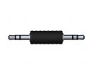
Connectors are components designed to securely link modules in a circuit, ensuring proper alignment and functionality. They prevent incorrect connections and mix-ups by providing a reliable and straightforward method for interconnecting electronic parts. With their simple design, connectors offer both efficient connectivity and enhanced safety, making them essential for maintaining the integrity and reliability of electronic systems. | |||
| Line 430: | Line 378: | ||
== 19. Port Cable == | == 19. Port Cable == | ||
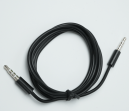
Cables are essential components used to transmit power and signals between electronic modules. Designed for flexibility and durability, they enable users to construct circuits with ease. | |||
| Line 443: | Line 389: | ||
== 20. Jumper Cable == | == 20. Jumper Cable == | ||
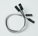
Jumper cables are used to bridge gaps or create custom routing in electronic circuits, offering flexibility in component connections. They allow for experimental circuit designs, enabling users to explore alternative pathways and configurations. | |||
| Line 456: | Line 400: | ||
== 21. Power Bank == | == 21. Power Bank == | ||
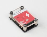
A compact and rechargeable source of energy for the entire kit. It makes the setup portable, safe, and kid-friendly. No wall sockets | A compact and rechargeable source of energy for the entire kit. It makes the setup portable, safe, and kid-friendly. No wall sockets needed, just plug in and go. | ||
| Line 470: | Line 413: | ||
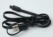
== 22. USB Type-C Cable == | == 22. USB Type-C Cable == | ||
Used to charge the power bank or connect to compatible devices. It’s modern, fast, and easy to use. One cable, many | Used to charge the power bank or connect to compatible devices. It’s modern, fast, and easy to use. One cable, many uses, just like in the gadgets they already know. | ||
= Building with Playtrons = | =Building with Playtrons= | ||
== Basic Projects == | ==Basic Projects== | ||
Starting with simple projects helps in understanding the components and their functionality. | Starting with simple projects helps in understanding the components and their functionality. | ||
# '''Star Projector''' | #'''Star Projector''' | ||
Explore LED module and a cardboard projector to create colorful light shows and cool visual effects. | Explore LED module and a cardboard projector to create colorful light shows and cool visual effects. | ||
| Line 490: | Line 429: | ||
Key Features: | Key Features: | ||
* Watch how light shines through shapes to make star pictures on your wall! | *Watch how light shines through shapes to make star pictures on your wall! | ||
* Create a mini star projector with just an LED and rolled-up cardboard! | *Create a mini star projector with just an LED and rolled-up cardboard! | ||
* Change the colors and cut new shapes to design your personal night sky! | *Change the colors and cut new shapes to design your personal night sky! | ||
== Advance Projects == | ==Advance Projects== | ||
After understanding the basics, more complex projects can be explored. | After understanding the basics, more complex projects can be explored. | ||
# '''Automatic Car break''' | #'''Automatic Car break''' | ||
Explore the automatic car brake system using a proximity sensor, conditional module and motor. | Explore the automatic car brake system using a proximity sensor, conditional module and motor. | ||
| Line 505: | Line 444: | ||
Key Features: | Key Features: | ||
* Discover how proximity sensors 'see' nearby objects like magic! | *Discover how proximity sensors 'see' nearby objects like magic! | ||
* Connect a sensor to a toy car's brakes - watch it stop automatically! | *Connect a sensor to a toy car's brakes - watch it stop automatically! | ||
= FAQs = | =FAQs= | ||
'''1. How do I start using Playtrons?''' | '''1. How do I start using Playtrons?''' | ||
Revision as of 10:39, 29 April 2025
Introduction
The Playtrons Kit is a vibrant introduction to the world of electronics, thoughtfully crafted for young learners in Grades 1 to 3. Designed to turn curiosity into creativity, this hands-on kit brings early STEM concepts to life without the need for coding. It comes loaded with safe, child-friendly sensors and actuators, allowing kids to build simple circuits, trigger movement, light up LEDs, and engage in real-world problem-solving—all through intuitive play.
Our kits are made to spark wonder, and Playtrons does just that by encouraging kids to explore technology with confidence. Whether in a classroom, after-school program, or at home, this kit provides a rich, tactile learning experience that promotes critical thinking, exploration, and discovery. While select components can be simulated using our PLODE platform, the true joy lies in hands-on interaction, where every connection fuels imagination.
Built for repeat use and designed to grow with the learner, the Playtrons Kit serves as an ideal gateway into STEM education. It helps young minds develop foundational skills in a playful yet structured way—laying the groundwork for future innovators, one circuit at a time.
Overview
Welcome to Playtrons, your child’s first step into the exciting world of electronics through hands-on discovery and playful experimentation. The Playtrons Kit is a screen-free learning tool designed for young learners in Grades 1 to 3, offering a safe and interactive introduction to basic electronic systems.
Built around simple plug-and-play components like sensors and actuators, Playtrons encourages kids to explore how things work by physically connecting parts and seeing real results—lights blinking, buzzers buzzing, and more. There’s no coding involved, just pure tactile learning.
The kit also integrates with the PLODE platform, allowing optional simulation of certain components for guided exploration. Whether used at school or at home, the Playtrons Kit makes foundational STEM learning fun, approachable, and endlessly engaging.
What's Inside the Box:
Open the box of the Playtrons Kit and let the adventure begin! Designed for young thinkers and little tinkerers, this kit is the perfect introduction to the world of electronics and STEM. With easy-to-use components and no coding required, kids can jump right into building simple circuits and exploring how things work—all through hands-on play. The Playtrons Kit comes with everything needed to spark imagination and curiosity, laying a fun and solid foundation for early tech learning.
Hardware
The Playtrons Kit comes with a fun set of plug-in sensors and actuators that bring each project to life. These components connect easily using simple ports, letting kids explore how different parts work together to create exciting effects—like making a light turn on with a button press or triggering a sound with a motion sensor. Each connection adds a new layer of discovery, helping young learners understand cause and effect through play. With its mix-and-match design, the Playtrons Kit encourages creativity, making it easy to build unique, interactive creations with real electronic parts.
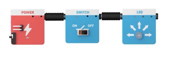
1. Power module
The power module serves as the central unit in any project, distributing power to all connected components. It regulates voltage to ensure stability and safety during operation. This allows users, especially beginners, to engage in experimentation without concerns about electrical safety. Simply connect the module to initiate the project, providing a reliable foundation for various electrical activities
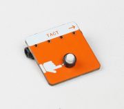
2. Tact Switch
This button is a component that sends a signal only when pressed, making it ideal for triggering actions such as illuminating an LED or activating a sound. This button is particularly useful for introducing users, especially beginners, to momentary input controls. Upon pressing, it initiates a brief response, enabling users to explore interactive electronic projects and their behavior.
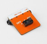
3. Switch
The toggle switch maintains a persistent state (on or off) until manually flipped to the opposite position. It is designed to teach users about stable states in electrical circuits. This switch is ideal for implementing simple on/off functions and power control in basic electronic projects, providing an introduction to more advanced concepts of circuit behavior and control mechanisms.
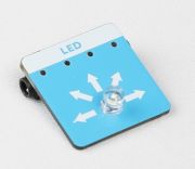
4. LED
The LED illuminates when supplied with power, providing a clear visual representation of electrical flow. It is commonly used as an indicator or alert in various electronic circuits. Safe and easy to use, the LED offers an engaging way for beginners to experiment with visual feedback mechanisms, enhancing their understanding of electrical concepts in hands-on projects.
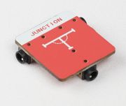
5. Junction
The junction is a connection point where multiple wires or components can converge, enabling more complex circuit designs. It facilitates the control of several outputs from a single input, streamlining circuit connections. Commonly used in applications requiring signal distribution, the junction acts as a central node, allowing multiple pathways for electrical signals to flow simultaneously within a system.
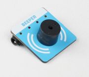
6. Beeper
The buzzer is an electronic component that produces sound when activated, commonly used for alerts or interactive feedback in circuits. It provides auditory responses to various events, enhancing the user experience in electronic projects. Often employed in systems requiring audio signals, such as alarms or notifications, the buzzer adds dynamic audio cues, increasing the engagement and interactivity of the project.
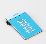
7. Counter
The counter is an electronic component designed to track the number of occurrences of an event, such as a button press or sensor activation. It is commonly used to demonstrate basic event tracking and memory functionality in electronics. This component allows users to measure and record the frequency of specific actions, enabling the study of behavior patterns over time in various applications.
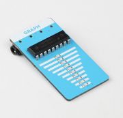
8. Graph
The graph module is a component that visually represents sensor data, such as temperature, light, or proximity, in a simplified format. It allows users, particularly beginners, to observe and interpret changes in real-time without the need for a screen. This tool serves as an introductory method for understanding data visualization, making it an effective learning aid for basic sensor-based projects.
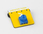
9. Greater Than Condition Module
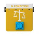
This smart module is designed to activate an output when a sensor reading exceeds a predefined threshold value. It introduces logical comparisons, such as "if the temperature exceeds 30°C, turn on the fan," enabling users to implement conditional actions. This module provides an engaging way to teach basic logic and sensor-driven control, offering an introductory experience to decision-making in electronic systems.
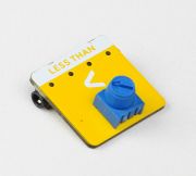
10. Less Than Condition Module
The less-than module triggers an output when a sensor reading falls below a specified threshold. It is commonly used in applications such as "if it's dark, turn on the light." This module facilitates the understanding of rule-based logic and critical thinking, offering an opportunity to implement conditional actions based on environmental conditions, making it ideal for sensor-based projects.
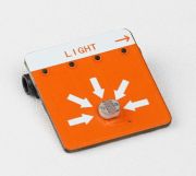
11. Light Sensor
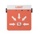
The light sensor detects ambient brightness levels and enables the creation of light-activated projects, such as automatic nightlights. It allows users to explore how electronic devices can respond to environmental changes, similar to how eyes detect light. This sensor is particularly useful in teaching fundamental concepts of environmental interaction and sensor-based automation in electronic circuits.
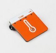
12. Temperature Sensor
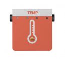
The temperature sensor measures heat levels, enabling the creation of temperature-sensitive projects. It can be utilized in a variety of applications, such as triggering devices like fans or buzzers based on temperature changes. This sensor provides an interactive learning experience, helping users understand thermal concepts and their practical applications in electronics and automation systems.
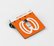
13. Magnetic Sensor
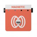
The magnetic sensor is a component that detects the presence of magnets or magnetic fields. It is commonly used in applications requiring invisible triggers or concealed switches. This sensor is ideal for interactive projects, such as games or hidden circuits, where magnetic fields are used to unlock or activate certain actions, providing an innovative way to incorporate magnetism into electronic designs.
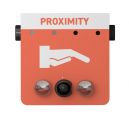
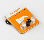
14. Proximity Sensor
The proximity sensor detects the presence of objects within a specified range without physical contact. It provides spatial awareness to a project, enabling it to respond to nearby movements. Commonly used in applications such as motion-activated lights, alarms, or distance-based actions, the proximity sensor offers an interactive way to integrate responsive behaviors in electronic systems and projects.
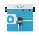
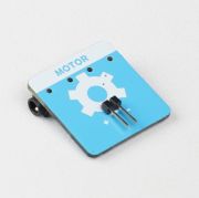
15. Motor Module
The motor control module regulates and powers a motor, allowing control over speed and direction. It is used to convert electrical signals into mechanical motion, enabling tasks such as spinning a propeller. This module serves as an introduction to robotics and movement control, providing essential functionality for building dynamic, motor-driven projects.
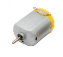
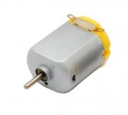
16. Motor
The motor converts electrical energy into mechanical motion, enabling movement in projects. Once connected, it initiates rotation, powering devices such as fans, spinners, or simple vehicles. This component is essential for introducing users to basic principles of energy conversion, demonstrating how electrical signals can drive motion in various mechanical applications, making it a key element in hands-on engineering projects.
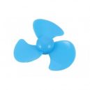
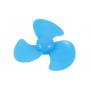
17. Propellor
The propeller, when attached to a motor, converts rotational motion into airflow, demonstrating how mechanical movement can produce tangible effects, such as moving air or cooling objects. This component is commonly used to illustrate basic principles of simple machines, providing an introductory experience in mechanical systems and motion-based applications. It serves as a practical tool for understanding the interaction between energy and physical movement.
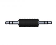
18. Port Connector
Connectors are components designed to securely link modules in a circuit, ensuring proper alignment and functionality. They prevent incorrect connections and mix-ups by providing a reliable and straightforward method for interconnecting electronic parts. With their simple design, connectors offer both efficient connectivity and enhanced safety, making them essential for maintaining the integrity and reliability of electronic systems.
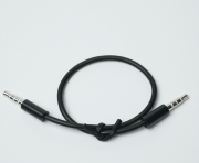
19. Port Cable
Cables are essential components used to transmit power and signals between electronic modules. Designed for flexibility and durability, they enable users to construct circuits with ease.
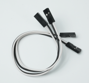
20. Jumper Cable
Jumper cables are used to bridge gaps or create custom routing in electronic circuits, offering flexibility in component connections. They allow for experimental circuit designs, enabling users to explore alternative pathways and configurations.
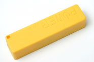
21. Power Bank
A compact and rechargeable source of energy for the entire kit. It makes the setup portable, safe, and kid-friendly. No wall sockets needed, just plug in and go.
22. USB Type-C Cable
Used to charge the power bank or connect to compatible devices. It’s modern, fast, and easy to use. One cable, many uses, just like in the gadgets they already know.
Building with Playtrons
Basic Projects
Starting with simple projects helps in understanding the components and their functionality.
- Star Projector
Explore LED module and a cardboard projector to create colorful light shows and cool visual effects.
Key Features:
- Watch how light shines through shapes to make star pictures on your wall!
- Create a mini star projector with just an LED and rolled-up cardboard!
- Change the colors and cut new shapes to design your personal night sky!
Advance Projects
After understanding the basics, more complex projects can be explored.
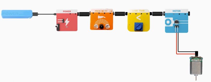
- Automatic Car break
Explore the automatic car brake system using a proximity sensor, conditional module and motor.
Key Features:
- Discover how proximity sensors 'see' nearby objects like magic!
- Connect a sensor to a toy car's brakes - watch it stop automatically!
FAQs
1. How do I start using Playtrons?
Connect the USB Type-C cable to the power module. Plug the other end of the cable into a power bank. Turn on the power bank and flip the power switch on the module to start using Playtrons!
2. How do I use the simulation tool?
The simulation tool lets kids test ideas digitally before building. Open it on a computer/tablet, drag components, and connect them virtually to see how they work!
3. Is Playtrons safe for kids?
Yes! Components are child-safe, but adult supervision is recommended. Avoid using damaged power banks or cables.
4. Can I make a robot?
"Not a full robot, but you can build a ""smart fan"": Use the temperature sensor to spin the motor when it’s hot!"
